Networking Search

Monday, August 10, 2009

Ensure Cisco router redundancy with HSRP

Ensure Cisco router redundancy with HSRP

by David "Davis CCIE, MCSE+I, SCSA"
(Apr 20, 2006)


Takeaway: What happens if your Internet router goes down and you lose all Internet access? That's why it's important to include redundancy in your network. In this edition of Cisco Routers and Switches, David Davis explains how you can use the Hot Standby Router Protocol (HSRP) to ensure redundancy.

People who read this, also read...

* Add network redundancy with Cisco HSRP
* Cisco networking 101: Five more things you should know


What happens if your Internet router goes down and you lose all Internet access? Is that acceptable for your organization? You can probably get away with it for about two minutes, but you need to have a better plan than just calling a support desk.

That's why it's important to include redundancy in your network. Consider adding a backup router to your current router that can take over at a moment's notice. All you need is the hardware, and the Cisco software can take care of the rest. Let's examine how to configure this using the Hot Standby Router Protocol (HSRP).

What is HSRP?

HSRP is a Cisco proprietary protocol for redundancy. It provides nearly 100 percent router availability and redundancy. So, if one router goes down, a backup router takes over the routing functions of the primary one.

However, there are other available industry protocols supported by Cisco. One industry standard is the Virtual Router Redundancy Protocol (VRRP). Another HSRP alternative is the Gateway Load Balancing Protocol (GLBP), another Cisco proprietary solution.


A sample network

Before we discuss how to configure HSRP, let's take a look at the network we'll use for this example. To help you better understand how HSRP works, here's a basic network diagram:


In our sample network, we've configured the PC's default gateway to IP address 10.1.1.3. However, that IP address doesn't point to a real device; instead, it serves as the virtual IP address for whichever router is the primary.

How does HSRP work?

When using HSRP, routers can either be primary or standby. If the primary router doesn't send out the HELLO packet to the standby router for a period of time, the standby router assumes the primary router is down and thus takes over. The standby router then assumes responsibility for the virtual IP address and begins responding to the virtual Ethernet MAC address to which the virtual IP address is pointing.

The primary and standby routers exchange HSRP HELLO packets so that each knows the other router is there. These HELLO packets use multicast 224.0.0.2 and UDP port 1985. The most basic form of HSRP has been available since IOS 10.0, but there have been newer features released in the 11 and 12 versions of the IOS.

What determines the active router? First, you can configure a priority number to determine it, and then it's by the highest IP address. The default priority number is 100; a higher priority number signifies the preferred router.

Of course, when setting up router redundancy, you aren't limited to just two routers. In fact, you can set up groups of routers that work together and have multiple "standby" routers.

How do you configure HSRP?

You can accomplish almost all HSRP configuration in the router's Interface Configuration Mode using the standby command. Let's look at the steps I took to configure the network shown in the diagram.

For Router 1:

1. Configure the IP address on the Ethernet interface.
2. Configure the standby IP address.
3. Configure standby preempt. (With preempt, Router 1 will always be the primary router as long as it's available.)

For Router 2:

1. Configure the IP address on the Ethernet interface.
2. Configure the standby IP address.
3. Configure standby priority to be less than 100. (In this case, it's 99.)

Now, let's look at the configuration for our sample network.

Router 1

(show running-config output)
interface Ethernet0/0
ip address 10.1.1.1 255.255.255.0
standby ip 10.1.1.3
standby preempt

Router1# show standby
Ethernet0/0 - Group 0
State is Active
2 state changes, last state change 00:00:29
Virtual IP address is 10.1.1.3
Active virtual MAC address is 0000.0c07.ac00
Local virtual MAC address is 0000.0c07.ac00 (default)
Hello time 3 sec, hold time 10 sec
Next hello sent in 0.692 secs
Preemption enabled
Active router is local
Standby router is 10.1.1.2, priority 99 (expires in 8.097 sec)
Priority 100 (default 100)
IP redundancy name is "hsrp-Et0/0-0" (default)

Router1#

Router 2

(show running-config output)
interface Ethernet0/0
ip address 10.1.1.2 255.255.255.0
standby ip 10.1.1.3
standby priority 99

Router2# show standby
Ethernet0/0 - Group 0
Local state is Standby, priority 99
Hellotime 3 sec, holdtime 10 sec
Next hello sent in 1.014
Virtual IP address is 10.1.1.3 configured
Active router is 10.1.1.1, priority 100 expires in 7.159
Standby router is local
4 state changes, last state change 00:02:02

Router2#

You can use the show standby command when in Privileged Mode to check the status of HSRP. This command tells you which router is active and which is standby, as well as a number of other statistics.

On the PC, the default IP address should point to 10.1.1.3—not either of the routers. This way, if one of the routers goes down, the other will take over. And you may even be able to use this redundancy to take production routers down during the day because the HSRP failover time is less than 10 seconds.

HSRP is a valuable tool for ensuring high availability and router redundancy. Of course, there are also several HSRP options that I didn't address in this article. For more information, check out the Cisco HSRP FAQ.


Miss a column?

Check out the Cisco Routers and Switches Archive, and catch up on David Davis' most recent columns.

Want to learn more about router and switch management? Automatically sign up for our free Cisco Routers and Switches newsletter, delivered each Friday!

David Davis has worked in the IT industry for 12 years and holds several certifications, including CCIE, MCSE+I, CISSP, CCNA, CCDA, and CCNP. He currently manages a group of systems/network administrators for a privately owned retail company and performs networking/systems consulting on a part-time basis.

source : www.techrepublic.com
Saturday, August 8, 2009

Preserve NAT translations when a Cisco router fails

Preserve NAT translations when a Cisco router fails

(by David "Davis CCIE, MCSE+I, SCSA")
(Apr 2006)


Takeaway: When you have two routers running HSRP, the standby router takes over if the active router goes down. But if this happens when you're using NAT, it severs all connections going through the active router. David Davis tells you how to use HSRP and SNAT to preserve these NAT translations.

Last time, I discussed how you can achieve Cisco router redundancy using the Hot Standby Router Protocol (HSRP). This time, let's delve a little deeper into your other HSRP options. If you're interested in using Network Address Translation (NAT) with HSRP, you should familiarize yourself with the Cisco IOS Stateful NAT (SNAT) feature, which helps provide higher availability and higher redundancy on your network when using NAT.

To quickly review, when you have two routers running HSRP, the standby router takes over if the active router goes down. However, if this happens when you're using NAT, it severs all connections going through the active router using dynamic NAT, and users would need to reestablish those connections. That's where SNAT comes in.


What is SNAT?

There's some confusion out there about what exactly SNAT stands for, and a Google search will return a variety of definitions. According to Microsoft, SNAT stands for Secure NAT and is available on ISA Server. In addition, SNAT can stand for Source NAT. However, in the Cisco arena, SNAT stands for Stateful NAT.

SNAT involves two or more routers performing the NAT function as a group. These NAT routers exchange information in their NAT translation databases with each other. You can view this information using the show ip nat translationscommand, whose output lists the protocol, inside global IP, inside local IP, outside local IP, and outside global IP.

Whenever a new NAT connection occurs via one of the NAT routers, the router relays that information to the others in the SNAT group. But these routers aren't just exchanging the IP addresses of the NAT IP flows; they're also exchanging the TCP state of those flows. The standby routers have already created the NAT translation table and are waiting for a failure on the active router.

In other words, the purpose for this exchange of NAT flow information is to ensure one of the standby NAT routers can take over if the active NAT router goes down. While you can configure SNAT in its own primary/backup mode, it works best when configured with HSRP.

Cisco has released SNAT in phases. In the first phase, released in Cisco in IOS 12.2(13)T, it only worked with protocols that didn't contain IP information in the application layer. But as of Cisco IOS 12.3(7)T, SNAT supports applications that have IP information embedded in the application layer, such as FTP. In addition, Cisco released some scalability enhancements for SNAT in IOS 12.4(4)T.

How do you configure SNAT?

To configure SNAT with HSRP, start by using the regular HSRP standby commands on your HSRP interfaces. You also need to configure an HSRP router with a group name of SNATHSRP to use the SNAT HSRP API.

Your standby command might look something like this:

standby name SNATHSRP
standby ip 10.10.10.1 secondary

You also need to ensure the full exchange of NAT state information between the routers in the SNAT group. Here's an example:

standby delay reload 60
standby 1 preempt delay minimum 60 reload 60 sync 60

After exiting Interface Configuration Mode, enter the ip nat stateful command; make sure it includes the same SNATHSRP group name. Here's an example:

ip nat stateful id 1
redundancy SNATHSRP
mapping-id 10

Now you can enter your standard NAT commands to create your translation pools. Here's an example:

ip nat pool snatpool1 10.10.10.1 10.10.10.9 prefix-length 24
ip nat inside source route-map rm-snat1 pool snatpool1 mapping-id 10 overload

Next, create your access control list and route map, according to the network for which you're configuring NAT. Here's an example:

access-list 101 permit ip 10.10.10.0 0.0.0.255 1.1.1.0 0.0.0.255

route-map rm-snat1 permit 10
match ip address 101

Finally, configure the other routers in your SNAT and HSRP pools to communicate. After that, you can use the traditional NAT commands such as show ip nat translations and show ip nat statistics, as well as the show ip snat command.

The combination of SNAT and HSRP working together preserves NAT translations when a failure occurs. A standby router can step in and take over the active role—possibly without users ever realizing there was a failure. Even better, you can be home asleep when it happens.
Want to learn more? Check out these Cisco resources


* Stateful Failover of Network Address Translation (SNAT) Phase 1
* NAT Stateful Failover for Asymmetric Outside-to-Inside and ALG Support—Stateful NAT Phase 2

* Scalability for Stateful NAT
* Configuring NAT for High Availability
* Enhanced IP Resiliency using Cisco Stateful NAT

Miss a column?

Check out the Cisco Routers and Switches Archive, and catch up on David Davis' most recent columns.

Want to learn more about router and switch management? Automatically sign up for our free Cisco Routers and Switches newsletter, delivered each Friday!

David Davis has worked in the IT industry for 12 years and holds several certifications, including CCIE, MCSE+I, CISSP, CCNA, CCDA, and CCNP. He currently manages a group of systems/network administrators for a privately owned retail company and performs networking/systems consulting on a part-time basis.

article source : www.techrepublic.com

Thursday, August 6, 2009

Learn to configure Cisco IOS NAT on a stick

Learn to configure Cisco IOS NAT on a stick

by : David Davis
(april 2008)

A well known NAT configuration is called “NAT on a stick.” Besides having a funny name, NAT on a stick can be very useful to network administrators. In this article, learn what NAT on a stick is and how it can help you.

What is Network Address Translation?

Network Address Translation (NAT) is used to translate IP addresses from one network into IP addresses for another network. NAT is performed by a router and is commonly used to translate private IP addresses used in homes and businesses into the public IP addresses that are used on the Internet.

When configuring NAT, there are a number of terms and concepts you need to know. For example: the difference between inside local, inside global, outside local, outside global, NAT vs. PAT, and “NAT overload.” You can learn about these terms and how NAT works, in my article, “Set up NAT using the Cisco IOS.” Additionally, you should take a look at the “Cisco IOS NAT order of Operations.”

I don’t recommend that you configure NAT on a stick until you have a good understanding of NAT. I recommend that you try one of the easier NAT configurations prior to NAT on a stick.

For more information on NAT, see the Cisco Systems white paper, “How NAT Works,” in TechRepublic’s white paper directory.


What is NAT on a stick?

First, the “stick” is just a single router interface. As NAT is typically performed between two router interfaces, NAT on a stick is used to describe a NAT configuration where a single router interface is used and NAT is performed. Thus, we are really talking about NAT on a single-router interface (but that’s not as catchy, is it?).

For NAT to work, a packet has to be sent from an inside NAT interface to an outside NAT interface. This is still true with NAT on a stick, but we are able to get around having only a single interface because we use a virtual interface to accomplish the same task. You use a policy-based route (PBR) to route and NAT the traffic between the virtual interface, which is a Cisco IOS loopback interface, and the physical interface.

Prior to configuring NAT on a stick, you should make sure that your Cisco IOS supports this feature. To do this, you can use the Cisco IOS Feature Navigator.

How can NAT on a stick help you?

NAT on a stick is not what I would consider a common configuration. However, I have seen it listed on Cisco certification exam objectives; I have heard Cisco instructors talk about it; and I have had readers ask me questions about it. So, even though you won’t find NAT on a stick in use on most enterprise networks, I think that it is important that you know what it is, how it can help you, and that it is yet another tool available to you, should you need it.

While there are a number of options for using NAT on a stick, here is a scenario in which I’ve seen it in use. (I have selected this scenario because it is based on the official Cisco documentation on this topic where you can go to find more information.)

You have a LAN with a number of computers, a single Cisco router with one Ethernet interface, and a cable DSL modem. Your ISP has given you a single IP address plus a block of two other IP addresses on a different network. Usually, you would get around this by using NAT (actually PAT or NAT overload) with a home/SMB router such as Linksys, Netgear, D-Link, or Belkin. But let’s say that you want to use a Cisco router only, and unfortunately, all you have is a 2501 (single Ethernet and Serial interface). The DSL modem is just a bridge (not a router) and the Cisco router cannot be connected directly to the cable modem because the router only has one LAN interface. You put a small hub in between the DSL modem and the 2501 Cisco router.

While this might sound like a wild scenario to some, and we all agree that you just need to buy more hardware — I don’t want to leave out any possible option that you could consider for using the Cisco IOS to solve a problem. Should this configuration be used on the Internet in production? No. Is it valuable to know how to configure NAT on a stick? Absolutely!

How do you configure NAT on a stick?

The sample configuration below for NAT on a stick is based on the following details: The local LAN is the 192.168.1.0 network. You are given one useable IP address on this network from the ISP, plus a block of two IP addresses on the 192.168.2.0 network. This network has access to the DSL modem. The 10.0.0.0 network is the LAN where you will have as many devices as you want and the devices on that LAN will rely on NAT on a stick.

Remember — the Cisco IOS loopback interface is the virtual interface that helps us get around the “one interface only” issue. Here is what you need to do:

Configure Interfaces with NAT statements and IP policy routing

interface Loopback0

ip address 10.0.1.1 255.255.255.252

ip nat outside

interface Ethernet0

ip address 192.168.1.2 255.255.255.0 secondary

ip address 10.0.0.2 255.255.255.0

ip nat inside

ip policy route-map nat-loop

Configure your NAT pools

ip nat pool external 192.168.2.2 192.168.2.3 prefix-length 29

ip nat inside source list 10 pool external overload

Ensure that you have IP Routes

ip route 0.0.0.0 0.0.0.0 192.168.1.1

ip route 192.168.2.0 255.255.255.0 Ethernet0

Create ACLs for NAT and the Policy Routing

access-list 10 permit 10.0.0.0 0.0.0.255

access-list 102 permit ip any 192.168.2.0 0.0.0.255

access-list 102 permit ip 10.0.0.0 0.0.0.255 any

Create the Route Map that is applied to the Ethernet interface

route-map Nat-loop permit 10

match ip address 102

set interface loopback0

With this configuration, the PC clients, assigned with 10.0.0.x network IP addresses will be NATed when their traffic arrives on the Ethernet0 interface. That NATing will use the 192.168.2.x pool.

You should note that you will have to configure the router’s primary Ethernet IP as the default gateway for all PCs in the NAT network. Also, you will also have to do ONE of the following:

1. Have the ISP or any other router on the other side of the NAT network create a static route for your 192.168.2.0/29, pointing to your router’s 192.168.1.2 IP address

2. Have your router advertise that network (in #1) via a dynamic routing protocol like RIP, OSPF, or EIGRP

This configuration is based on the example provided in Cisco’s official Network Address Translation on a Stick documentation. Please review it if you have questions on this example as it has a diagram and debug steps.

In Conclusion

NAT on a Stick is one of the many tools that a network admin may need to employ in certain situations. If nothing else, it is a configuration that you should recognize by name if you are asked about it on certification exams or by colleagues. For some admins, it is an irreplaceable tool.

Want to learn more about router and switch management? Automatically sign up for our free Cisco Routers and Switches newsletter, delivered each Friday!

David DavisDavid Davis has worked in the IT industry for 15+ years and holds several certifications, including CCIE, CCNA, CCNP, MCSE, CISSP, VCP. He has authored hundreds of articles and numerous IT training videos. Today, David is the Director of Infrastructure at Train Signal.com. Train Signal, Inc. is the global leader in video training for IT Professionals and end users. Read his full bio and profile.

article source = www.techrepublic.com

Wednesday, August 5, 2009

Understand the order of operations for Cisco IOS

Understand the order of operations for Cisco IOS

by David "Davis CCIE, MCSE+I, SCSA"
(Mar 2006)

Takeaway: Being familiar with the Cisco IOS order of operations is vital when it comes to understanding how the traffic within a router is flowing and how to control that traffic. This week, David Davis walks you through the two different order of operations tables: the NAT Order of Operations and the QoS Order of Operations.

The Cisco IOS order of operations plays an important role in how a router processes traffic. The order of operations tells the router how to process traffic according to the configuration of different router features.

If you're simply using the most basic features of the router, chances are good that you'll never have to think about the order of operations. However, when configuring features such as Network Address Translation (NAT), Quality of Service (QoS), and encryption, it's essential to understand the order of operations in order to configure these features successfully.

Using the Cisco IOS actually involves two different order of operations tables: the NAT Order of Operations and the QoS Order of Operations. Let's take a look at each.


NAT Order of Operations

Before you can understand the NAT Order of Operations list, you first need to understand NAT itself. In its most basic form, NAT translates one IP address to another IP address.

When the router uses this order of operations, it takes the inbound packet, starting at the top and moves down the list. If the packet is from a NAT inside-designated interface, it uses the inside-to-outside list. If the packet is from an outside-to-inside interface, it uses that list.

Here's the order of operations for the inside-to-outside list:

* If IPSec, then check input access list
* Decryption—for Cisco Encryption Technology (CET) or IPSec
* Check input access list
* Check input rate limits
* Input accounting
* Policy routing
* Routing
* Redirect to Web cache
* NAT inside to outside (local to global translation)
* Crypto (check map and mark for encryption)
* Check output access list
* Inspect context-based access control (CBAC)
* TCP intercept
* Encryption

Here's the order of operations for the outside-to-inside list:

* If IPSec, then check input access list
* Decryption—for CET or IPSec
* Check input access list
* Check input rate limits
* Input accounting
* NAT outside to inside (global to local translation)
* Policy routing
* Routing
* Redirect to Web cache
* Crypto (check map and mark for encryption)
* Check output access list
* Inspect CBAC
* TCP intercept
* Encryption

Let's say that you have an IP packet coming in from an outside-to-inside interface. When translating that packet, you want to use an access control list to block traffic from certain IP addresses. Which IP address should you put in the ACL—the IP address before the packet's translation (i.e., the public IP address), or the IP address after the packet's translation (i.e., the private address)?

By checking the order of operations, you can determine that the "NAT outside to inside" operation occurs after the "Check input access list" task. Therefore, you would use the public IP address in the ACL because the packet hasn't gone through NAT.

On the other hand, what if you want to create a static route for traffic going through NAT? Should you use the public (outside) or private (inside) IP address? In this case, you would use the private (inside) IP address because the traffic has already gone through NAT when it gets to the "Routing" operation.


QoS Order of Operations

The Quality of Service (QoS) order of operations is another important list to know. Of course, this is only really important if you're using QoS. But if you are, you need to be familiar with it.

Here's the order of operations for inbound traffic to the router:

* QoS Policy Propagation through Border Gateway Protocol (BGP)—or QPPB
* Input common classification
* Input ACLs
* Input marking—class-based marking or Committed Access Rate (CAR)
* Input policing—through a class-based policer or CAR
* IPSec
* Cisco Express Forwarding (CEF) or Fast Switching

Here's the order of operations for outbound traffic from the router:

* CEF or Fast Switching
* Output common classification
* Output ACLs
* Output marking
* Output policing—through a class-based policer or CAR
* Queueing—Class-Based Weighted Fair Queueing (CBWFQ) and Low Latency Queueing (LLQ))—and Weighted Random Early Detection (WRED)

Being familiar with the order of operations is vital when it comes to understanding how the traffic within a router is flowing and how to control that traffic. In my experience, the NAT order of operations is most important when you're using any combination of NAT, crypto, ACLs, routing, or other features on the list.

Without a proper understanding of the order of operations, you can spend an entire week troubleshooting a basic NAT and ACL combination—without any luck. Knowing about the order of operations can really make a difference.


Miss a column?

Check out the Cisco Routers and Switches Archive, and catch up on David Davis' most recent columns.

Want to learn more about router and switch management? Automatically sign up for our free Cisco Routers and Switches newsletter, delivered each Friday!

David Davis has worked in the IT industry for 12 years and holds several certifications, including CCIE, MCSE+I, CISSP, CCNA, CCDA, and CCNP. He currently manages a group of systems/network administrators for a privately owned retail company and performs networking/systems consulting on a part-time basis.

source : www.techrepublic.com
Tuesday, August 4, 2009

Set up Port Address Translation (PAT) in the Cisco IOS

Set up Port Address Translation (PAT) in the Cisco IOS

by David Davis CCIE, MCSE+I, SCSA
(May 2007)

Takeaway: NAT is a valuable tool for admins, both for conserving public IP addresses and securing internal resources. Several variations of NAT are available, including its cousin PAT. See the differences and learn how to set up PAT using the Cisco IOS.


* Set up NAT using the Cisco IOS
* Configure static NAT for inbound connections
* Learn to configure Cisco IOS NAT on a stick
* Using NAT to connect Windows 2003 to the Internet
* Configure IT Quick: Configuring Routing and Remote Access on your Windows 2000 server


Port Address Translation (PAT) is a special kind of Network Address Translation (NAT). It can provide an excellent solution for a company that has multiple systems that need to access the Internet but that has only a few public IP addresses. Let's take a look at the distinctions between NAT and PAT and see how they are typically used. Then, I'll show you how to configure PAT on a Cisco router.

Understanding PAT and NAT

Before discussing PAT, it will help to describe what NAT does in general. NAT was designed to be a solution to the lack of public IP addresses available on the Internet. The basic concept of NAT is that it allows inside/internal hosts to use the private address spaces (10/8, 172.16/12, and 192.168/16 networks—see RFC1918), go through the internal interface of a router running NAT, and then have the internal addresses translated to the router's public IP address on the external interface that connects to the Internet.

If you dig into NAT a little deeper, you will discover that there are really three ways to configure it. From these configurations, you can perform a variety of functions. The three configurations are:

PAT
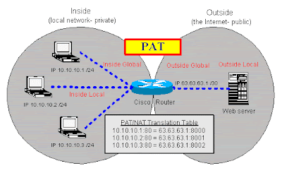
PAT is commonly known as “NAT overload” (or sometimes just “overload”). In this configuration, you have multiple clients on your inside network wanting to access an outside network (usually the Internet). You have few public IP addresses, many more than the number of clients, so you have to “overload” that real Internet IP address. In other words, you are mapping many inside clients to a single Internet IP address (many to one). For an illustration of PAT, see Figure A.

Figure A


Pooled NAT

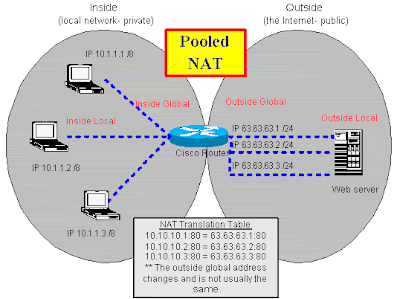
Pooled NAT is similar to PAT except you have the luxury of having a one-to-one mapping of addresses. In other words, you have just as many inside network clients as you do outside network IP addresses. You tell the NAT router the pool of IP addresses that are available, and each client receives its own IP addresses when it requests a NAT translation. The client does not get the same address each time it requests a translation; it merely gets the next available address from the pool. In my article "Set up NAT using the Cisco IOS," I explain how to configure Pooled NAT. For an illustration of Pooled NAT, see Figure B.


Figure B


Static NAT

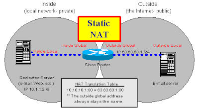
Static NAT is the simplest form of NAT. The most likely example is a mail server on the inside of a private network. The private network connects to the public Internet. In between the two networks, a router performs NAT. For a dedicated server, like a mail server, you would want a static (not changing) IP address. This way, every time someone on the Internet sends e-mail to the mail server, that server has the same public IP address. For an illustration of Static NAT, see Figure C.

Figure C


As I said, you can perform a variety of functions with these three configurations. For the purpose of this article, we will focus on configuring PAT.

Configuring PAT

To configure PAT/NAT correctly the first time, you need to understand the Cisco NAT terminology and how your IP networks/addresses map to each of the entities listed below:

* Inside Local—This is the local IP address of a private host on your network (e.g., a workstation's IP address).

* Inside Global—This is the public IP address that the outside network sees as the IP address of your local host.

* Outside Local—This is the local IP address from the private network, which your local host sees as the IP address of the remote host.

* Outside Global—This is the public IP address of the remote host (e.g., the IP address of the remote Web server that a workstation is connecting to).


You'll configure your Cisco router using seven commands. Let's assume that your Internet service provider gave you a 30-bit network containing two public IP addresses. This configuration would allow one address for your router and one address for your internal clients and devices. The first command you'll execute will tell the router which public IP address you want to use for PAT:

ip nat pool mypool 63.63.63.2 63.63.63.2 prefix 30

This command configures a pool (range) of IP addresses to use for your translation. In this case, we want only one address in our pool, which we will overload. We do this by assigning the same IP address (63.63.63.2) for the start and end of the pool.

The next command will tell your router which IP addresses it is allowed to translate:

access-list 1 permit 10.10.10.0 0.0.0.255

It's not a good idea to put “permit any” in the access list, even though you will occasionally see that as a recommendation in some sample configurations.

The next command is:

ip nat inside source list 1 pool mypool overload

This command puts the pool definition and the access list together. In other words, it tells the router what will be translated to what. The overload keyword turns this into a PAT configuration. If you left out overload, you would be able to translate only one IP address at a time, so only one client could use the Internet at a time.

Next, you need to tell PAT/NAT what interfaces are the inside network and what interfaces are the outside network. Here's an example:

interface ethernet 0
ip nat inside


interface serial 0
ip nat outside

With these commands, your PAT configuration is finished. You have told the Cisco IOS you are translating your network A into a single IP address from network B, that network A is on the ethernet 0 interface and network B is on the serial 0 interface, and that you want to allow the inside network to overload the single IP address on the outside network.

Finally, verify that NAT works. This can be as simple as doing a ping command from your inside local host to an outside global host. If the ping succeeds, chances are you have everything configured correctly. You can also use the following Cisco IOS commands to confirm and troubleshoot:

show ip nat translations [verbose]
show ip nat statistics

With the translations command, you should see the translation that was created from your ping test. But watch out: The translations will disappear after their time-out expires. If you have configured overload, these time-outs are configurable by traffic type.

Summary

You should now understand the differences between PAT, Pooled NAT, and Static NAT, and you should be able to do a basic PAT configuration with the Cisco IOS. For more information, check out the links below.

source : www.techrepublic.com

Saturday, August 1, 2009

Set up NAT using the Cisco IOS

Set up NAT using the Cisco IOS

by David Davis CCIE, MCSE+I, SCSA
(october 2001)

Takeaway: Network address translation (NAT) has become one of the key components of today's corporate networks attached to the Internet. See how to set up and manage NAT using the Cisco Internetwork operating system.

Network address translation (NAT) is one of those rare information technology buzzwords that does exactly what its name implies. In this case, it translates one network address into another network address. The most popular use for NAT is to connect an internal network to the Internet. The proliferation of hosts that now connects to the Internet is causing a shortage of IP addresses, so NAT is a key tool for connecting corporate networks using private IP addresses to the Internet. Since Cisco provides the bulk of the routers that connects to the Internet, we’re going to show you how to set up NAT using the Cisco Internetwork Operating System (IOS).

Understanding NAT

Using NAT to connect to the Internet allows you to:

* Use only one public, registered IP address for Internet access for many thousands of private IP addresses at your site.

* Change Internet service providers (ISPs) easily, without readdressing the majority of hosts on your network.

* Hide the identity of hosts on your local network behind the single public IP address to keep outside hosts from easily targeting them.


The most difficult part of using NAT in the Cisco IOS is getting a handle on these four key terms:

* Inside Local—This is the local IP address of the private host on your network (i.e., your PC’s IP address).

* Inside Global—This is the public, legal, registered IP address that the outside network sees as the IP address of your local host.

* Outside Local—This is the local IP address from the private network, which your local host sees as the IP address of the remote host.

* Outside Global—This is the public, legal, registered IP address of the remote host (i.e., the IP address of the remote Web server that your PC is connecting to).


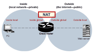
My first reaction after reading Cisco’s definitions for these terms was nearly total confusion, so don’t feel bad if you feel the same thing. But after seeing a diagram of these terms, it started to click for me. Take a look at Figure A for a logical diagram of these terms.

Figure A


Configuring NAT

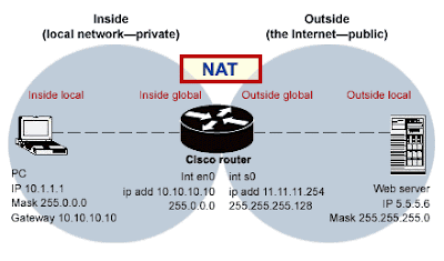
To configure the standard NAT scenario I mentioned in the opening paragraph, refer to Figure B and then look at the simple steps that need to be taken if you are using a Cisco router between your local network and the Internet.

Figure B


1. · Configure your pool of legal, public IP addresses that the router can use to represent your local addresses on the Internet. This pool can contain as few as one or as many addresses as you would like to provide. For a small to medium-size network, one address is typically fine. The syntax is:

ip nat pool name start-ip end-ip {netmask netmask | prefix-length prefix-length}


1. Define an access-list to specify what range of IP addresses is allowed to be translated from your local network to the remote network. This is, basically, a security feature asking you, “Who (what range of IP addresses) can use the NAT service?” The syntax is:

access-list access-list-number permit source [source-wildcard]

1. Specify that you want a dynamic translation from the source IP address to the pool and that you want to overload the pool address (or addresses). The syntax is:

ip nat inside source list access-list-number pool name overload

1. · Specify which of the router’s interfaces will be the “inside” address. The syntax for the Ethernet 0 interface is:

int en0
ip nat inside

1. · Specify which of the router’s interfaces will be the “outside” address. The syntax for the Serial 0 interface is:

int s0
ip nat outside

1. · Add a static route to your router to send any traffic not destined for your local network to the Internet interface. (In our case, I will use a default route to send traffic out the serial interface.) Here’s the syntax:

ip route 0.0.0.0 0.0.0.0 serial0

Listing A shows the resulting configuration for the router. One way to examine this on your router would be to issue the command show run.

How is this possible?

This configuration would allow any host on your local network (such as a desktop PC) to connect to the Internet using the single registered IP address that is being overloaded. Thus, any traffic from that local PC will have the source IP address of the router’s external interface.

If you think about this for a minute, you might wonder how multiple hosts can share the same IP address in the overload configuration, since we are taught that one IP address is assigned to one host and there is no sharing (anymore than there is sharing of a social security number).

The answer to that question is that NAT gets around this rule by making an entry in a translation table for every host using a port. In this translation table, there is a map between the inside local, a port on the inside global, another port on the outside local, and the outside global. By assigning these ports and keeping track of them in the table, the router is able to “overload” a single IP address with multiple hosts. This allows them to share a single IP address among them.

You can learn more about NAT and how to configure the other two possible uses of NAT from the Cisco Tech Tips pages and from the online Cisco IOS documentation pages on configuring IP addressing and IP addressing commands.

source : www.techrepublic.com